



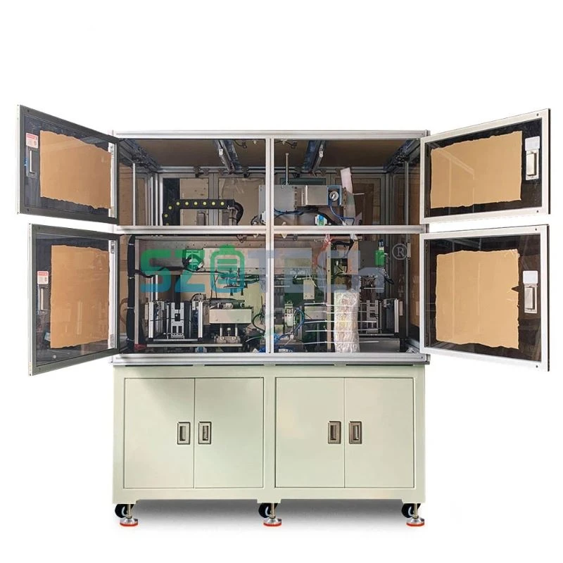
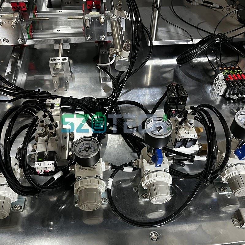
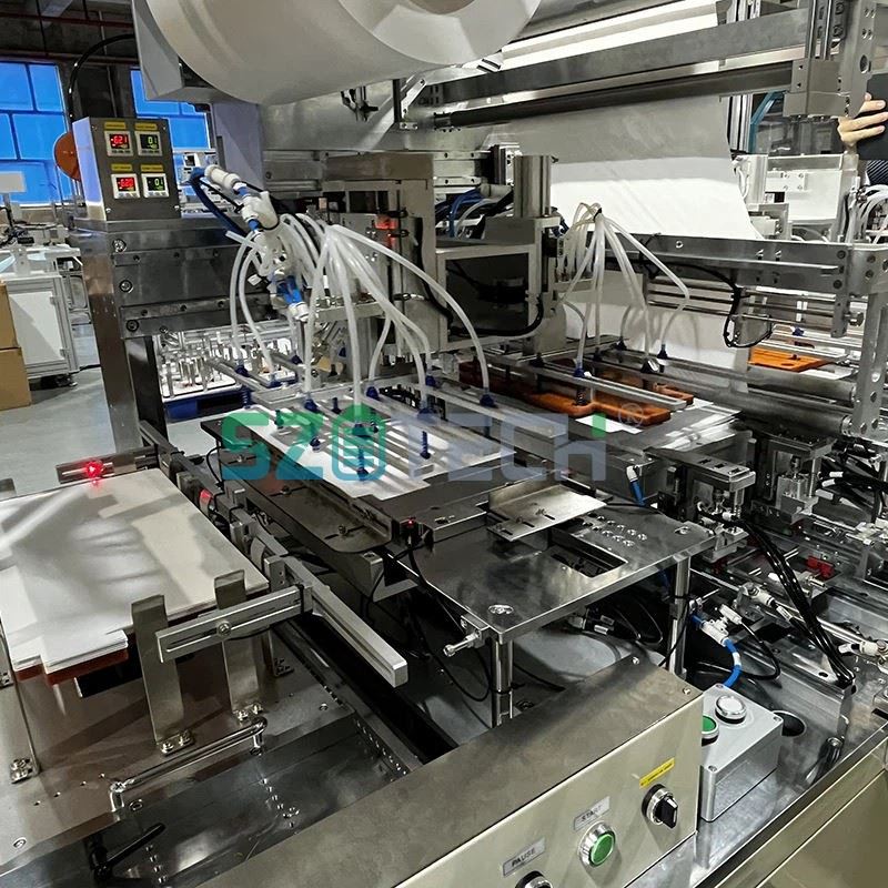


The JD-ZDP-2020 battery stacking machine uses a Z-fold process to assemble positive electrode sheets, negative electrode sheets and separator film into a stacked cell. Servo-driven manipulators transfer the electrode sheets from their respective material boxes to the positioning area, while a tension-controlled unwinding mechanism feeds the separator.
During stacking, the positive and negative electrode sheets are arranged with the separator on the main stacking platform. The platform moves downward as the stack builds up to maintain the working position. After stacking, a hot knife cuts the separator, and the cell moves to the U-shaped taping station before being transferred to the feeding platform.
The electrode positioning area includes dust removal and double-sheet detection. An ultrasonic detector can trigger an alarm and stop the machine when it detects multiple sheets. The positioning unit has a stated accuracy of ±0.1 mm. The separator correction system uses a sensor with a stated precision of ±0.1 mm and provides a correction range of ±20 mm.
Separator tension is adjustable from 10–150 N. The unwinding section also includes electrostatic removal to help reduce dust attraction. Covered guide rails and a screw-driven transfer mechanism are used in the electrode handling area.
At the taping station, the cell is held in position while U-shaped tape is applied to its edge. The tape application length is adjustable, and the finished cell is then transferred to the feeding platform.
Equipment Parameters
| Item | Specification |
|---|---|
| Model | JD-ZDP-2020 |
| Cell thickness | 2.5–75 mm |
| Cell width | 60–200 mm |
| Cell length | 100–220 mm, excluding ear height |
| Sheet stacking speed | ≤2.0 s/pcs |
| Electrode and separator alignment | Longitudinal central deviation <0.5 mm |
| Inter-gap alignment accuracy | ±0.3 mm |
| Single-pair alignment accuracy | ±0.4 mm |
| Overall electrode alignment accuracy | ±0.5 mm |
| Auxiliary cell completion time | ≤30 s |
| Equipment availability | ≥98% |
| Pass rate, excluding defective incoming materials | ≥99.5% |
| Separator tension | 10–150 N |
| Diaphragm correction range | ±20 mm |
| Diaphragm correction system positioning accuracy | ±0.2 mm |
| Positioning accuracy | ±0.1 mm |
Main Mechanisms
Electrode Material Handling
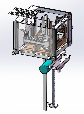
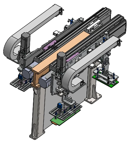
Separate positive and negative electrode material boxes are provided on the machine. The material box area includes dust removal and multi-sheet prevention. Servo-driven manipulators pick the electrode sheets from the storage boxes, transfer them to the positioning platforms and then place them on the stacking platform.
The positioning platforms use suction, dust removal and ultrasonic detection. If multiple electrode sheets are detected, the system can issue an alarm and stop the equipment for inspection.
Separator Unwinding and Correction
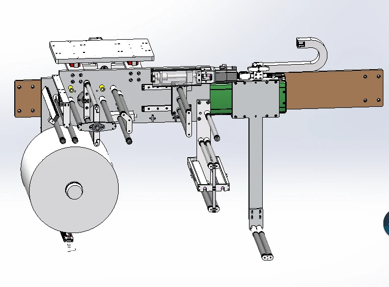
The separator is passively unwound, with an alarm when the material supply is insufficient. An adjustable pressure cylinder and floating roller control separator tension in real time within the 10–150 N range.
The unwinding assembly is mounted on the correction platform. The correction sensor has ±0.1 mm precision, while the correction system provides ±0.2 mm positioning accuracy and ±20 mm correction range. An electrostatic removal device is also installed in the separator unwinding section.
Z-Fold Stacking
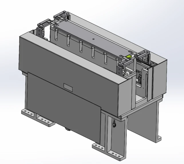
The main stacking platform is motor-driven and moves vertically as the stack builds. Its lifting mechanism is positioned at the center of the platform so that the load is distributed during pressing.
The stacking pressure can be adjusted according to the electrode and separator materials. As the stacking thickness increases, the platform position is lowered to maintain the working height.
Separator Hot Cutting
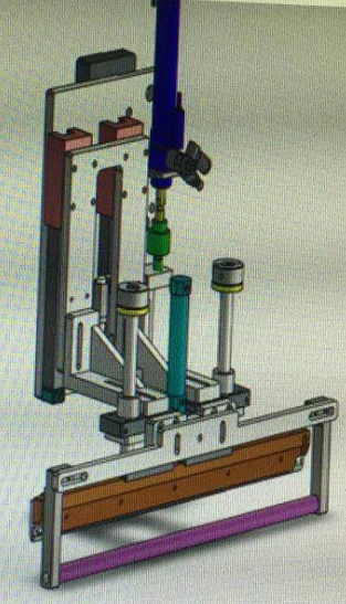
The separator cutting assembly uses a heated nickel-chromium blade. The cutting process is designed to avoid cracks, warping and drawing on the separator. The stated blade service life is more than 100,000 cuts.
U-Shaped Taping
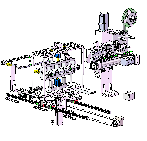
After hot cutting, a transfer mechanism moves the cell to the taping station. The cell remains clamped while U-shaped tape is applied to its edge. The tape length can be adjusted, and the mechanism is designed to keep the tape flat without obvious separator wrinkles.
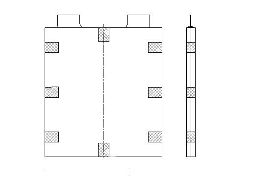
Adhesive tape diagram
Cell Feeding and Safety Cover
After taping, the cell is transferred to the feeding platform. The equipment cover uses aluminum profiles and acrylic panels and is fitted with access-control switches. Opening a cover door stops machine operation.
Control and Main Components
The machine uses PLC control with a touch screen and button-based operation. The listed main components include HIWIN linear guide rails and screws, Hui Chuan servo motor and drive, KEYENCE PLC and fiber-optic components, Panasonic sensors, Yadek air cylinders and electromagnetic valves, and a Viluton touch screen.
Electrical circuit drawings, equipment manuals, maintenance information, qualification documents, electrical schematics and vulnerable-part drawings are supplied with the equipment.
Key Components
System structure composition and description:
|
Order number |
Component name |
Quantity |
Explain |
|
1 |
Module block |
1 |
Provide support and installation reference for equipment |
|
2 |
Positive/negative electrode material box assembly |
2 |
One positive and one negative material box (standard on each machine) |
|
3 |
Positive/negative electrode mechanical positioning components |
2 |
The electrode is placed on the positioning platform for mechanical and precise positioning |
|
4 |
Mechanical handle material handling unit |
2 |
The robotic arm retrieves materials from the storage box and transfers them to the secondary positioning platform, then moves them to the stacker platform. |
|
5 |
Diaphragm unwinding assembly |
1 |
The diaphragm is controlled by the motor to passively unwind and has the function of overall correction |
|
6 |
Main lamination table assembly |
1 |
The positive and negative electrodes and the diaphragm are stacked in a Z-shaped manner |
|
7 |
Diaphragm cutting assembly |
1 |
The diaphragm is cut with a hot knife, and there is no crack or curl after cutting |
|
8 |
Feeding manipulator assembly |
1 |
Place the cell from the stacking table to the hot cutting mechanism, and place it from the hot cutting position to the adhesive mechanism |
|
9 |
Adhesive assembly |
1 |
The edge of the battery cell is wrapped with U-shaped tape, and the number of U-shaped tapes can be set. |
|
10 |
Cell feeding assembly |
1 |
Place the coated cell into the feeding platform |
|
11 |
hood |
1 |
Provide a relatively sealed environment for the device with access control |
|
12 |
PLC and HMI control system |
1 |
PLC bus control with touch screen and buttons |
System Structure and Mechanisms
1. Rack Module:
The system comprises three key components: the main rack structure, a standardized mounting plate, and an HMI unit. The rack structure provides structural support for the entire equipment. The mounting plate, constructed from 25mm-thick steel plate, serves as a unified installation surface and reference point for other subsystems. The HMI unit controls the equipment's operational functions.
2. Positive/negative electrode box mechanism:
3. Mechanical hand material handling mechanism:
4. Diaphragm unwinding mechanism:
5. Main folding platform mechanism:
6. Diaphragm cutting mechanism:
7. Cutting machine mobile mechanism:
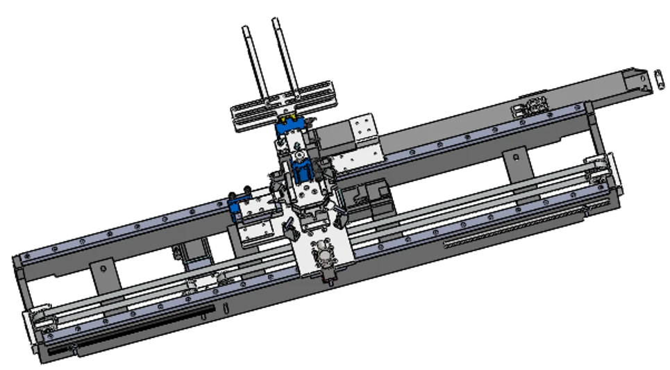
The transfer mechanism moves the cell from the laminating table to the hot cutting position and then transfers it to the adhesive mechanism after hot cutting.
8. Adhesive mechanism:
9. Cell feeding mechanism:
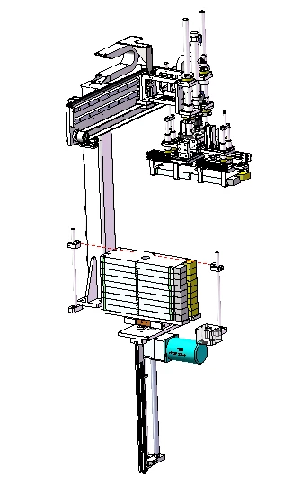
The material handling unit places the taped cell on the feeding platform.
Equipment accessories
1. Electrical circuit drawings (delivered with the equipment).
2. Standard parts and main configuration table (Appendix).
|
Order number |
Component Name |
Manufacturers |
|
1 |
air cylinder |
Yadek |
|
2 |
magnetic switch |
domestic |
|
3 |
linear guide rail |
HIWIN |
|
4 |
Hand/linear screw |
HIWIN |
|
5 |
Servo motor/drive |
Hui Chuan |
|
6 |
electromagnetic valve |
Yadek |
|
7 |
PLC |
KEYENCE |
|
8 |
sensor |
Panasonnic |
|
9 |
fibre-optical |
KEYENCE |
|
10 |
touch screen |
Viluton |
3. List of vulnerable parts.
|
Order number |
name |
model |
quantity |
unit |
|
1 |
photoelectric switch |
PM-L25 |
2 |
PCS |
|
2 |
auxiliary relay |
RXM2LB2BD DC24V 8 pin |
1 |
PCS |
|
3 |
electromagnetic valve |
Adak |
1 |
PCS |
|
4 |
magnetic switch |
D-M9BL |
1 |
PCS |
|
5 |
vacuum slot |
PAG15 |
2 |
PCS |
|
6 |
molybdenum filament |
2 |
M |
4. Random item list.
|
Order number |
Name of material (data) |
copies |
submission time |
remarks |
|
1 |
Special debugging and maintenance tools |
1 set/unit |
At delivery |
Hex key 1 set/pc |
|
2 |
Device Operation Manual: (including the following) 1. Equipment description and instruction manual; 2. Equipment Maintenance and Maintenance Manual: Introduction to the working principle of the equipment; General mechanical layout diagram, component assembly diagram; lubrication maintenance specification |
1 set |
Delivery or equipment Before delivery and use |
|
|
3 |
Loading list and product qualification certificate |
1 set |
At delivery |
|
|
4 |
Electrical schematic |
1 copy |
End of warranty After receiving full payment |
|
|
5 |
Drawings of vulnerable parts and spare parts |
1 copy |
At delivery |
Some vulnerable parts are provided in PDF size drawings |