This 128-channel Lithium battery grading and aging cabinet is engineered for high-volume capacity grading (grading) and aging of cylindrical battery cells (e.g., 18650, 21700, 26700). Each channel provides independent 5V, 6A output for precise charge-discharge cycling, enabling accurate capacity measurement, sorting, and performance stabilization. The system supports programmable test profiles to simulate various formation and aging conditions. With integrated temperature monitoring, comprehensive data logging for each cell, and robust safety protections, it ensures reliable batch processing and superior consistency. Its high channel count and automated operation make it an ideal, efficient solution for quality control in medium to large-scale cylindrical cell production lines.
Production Model: SZO-5V6A-128CH-10-60H

Overall Dimensions and Appearance Drawing of the Equipment (The dimensions and image are for reference only; the 3D model shall prevail.)
Technical Parameters
| 1. Equipment Technical Parameters Suitable Battery Range: Diameter 18–32 mm, Height 60–140 mm |
|
|
Sample Limitations |
This testing equipment is prohibited from: Testing or storing samples of flammable, explosive, or volatile substances. Testing or storing samples of corrosive substances. Testing or storing samples of strong electromagnetic radiation-emitting sources. Testing or storing samples of radioactive materials. Testing or storing samples of highly toxic substances. Testing or storing samples that may produce any of the above-mentioned substances or objects during the testing or storage process. |
|
2,Volume, Dimensions, and Weight |
|
|
2.1 Nominal Volume |
500L |
|
2.2 Inner Dimensions |
W810 mm×D400 mm×H1550 mm |
|
2.3 Overall Dimensions |
W1260 mm×D1060 mm×H1960 mm (Excluding Projections) |
|
2.4 Net Weight |
About 650kg |
|
3,Performance |
|
|
3.1 Temperature Range |
0~85℃ |
|
3.2 Temperature Fluctuation |
≤±2℃(Under No-Load, with Stable Temperature) |
|
3.3 Temperature Deviation |
±3.0℃(Under No-Load, with Stable Temperature) |
|
3.4 Heating Time |
25℃→85℃ ≤40 min(No-Load, Average Non-Linearity) |
|
3.5 Cooling Time |
25℃→0℃ ≤50 min(No-Load, Average Non-Linearity) |
|
3.6 Thermal Load |
≤500W (Caused by Heat Generation when the Battery Cell is Powered) |
|
4,Structural Features |
|
|
4.1 Insulated Enclosure Structure |
External Wall Material: High-quality cold-rolled steel plate with surface coating (painted finish) |
|
4.2 Air Regulation Channel |
Axial Flow Fan, Heater, Evaporator |
|
4.3 Standard Configuration |
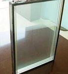
Lead Holes (with Soft Rubber Plugs): Located on the left and right sides at the back of the enclosure, with 2 holes for each tray layer. Caster Wheels: 4 casters (with brakes). Observation Window: Double-layer hollow electric heat film anti-fog observation window (located on the door). Visible Area: Approximately 420 × 600 mm (W × H), with electric anti-fogging film on the glass for optimal observation clarity. Battery Tray: 8 layers of electrically insulated battery trays, weight capacity (evenly distributed): 15 kg/layer. Lighting: LED lighting.
|
|
4.4 Control Panel |
Touch control buttons, emergency stop buttons, etc. |
|
4.5 Heater |
Nickel-Chromium Alloy Resistance Wire Heater |
|
5,Refrigeration System |
|
|
5.1 Refrigeration Compressor |
Fully Hermetic Reciprocating Compressor |
|
5.2 Cooling Method |
Air-Cooled |
|
5.3 Throttling Device |
Capillary Tube |
|
5.4 Refrigerant |
R404A |
|
5.5 Welding Process |
Nitrogen Protective Welding |
|
6,Electrical Control System |
|
|
6.1 Controller |
Touch Controller (Independently Developed by NEWARE)+Button-type Controller |
|
6.2 Setting Method |
Touch Key Type |
|
6.3 Control Method |
Forced Circulation Ventilation and Balanced Temperature Control Method. |
|
6.4 Communication Method |
Ethernet standard interface |
|
6.5 Temperature control module |
Independently Developed (Tested for Reliability with High and Low Temperature Shock, Vibration, EMC, and Other Related Performance Tests) |
|
7,Safety Protection Device |
|
|
Test Chamber |
Leakage Protection, Short Circuit Protection, and Abnormal Operation of Circulating Fan, etc. |
|
8,Other Configurations |
|
|
8.1 Power Cable |
One 5-core Cable (Three-Phase Four-Wire + Protective Earth Wire) (Specific Specifications to be Selected According to Contract Requirements) |
|
8.2 Main Power Leakage Circuit Breaker |
Three-Phase Four-Wire + Protective Earth Line |
|
9,Transportation The test chamber is of an integrated design, and will be shipped as a whole. |
|
|
Size |
Maximum Shipping Dimensions (Excluding Packaging): "See Section 2.3 Dimensions" |
|
10,Operating Conditions: The user is responsible for ensuring the following conditions (installation of the power supply lines for the equipment is the responsibility of the user). |
|
|
10.1Installation Site |
The ground must be level, with flatness ≤ 5mm/2m. |
|
10.2 Environmental Conditions |
Temperature: 5°C to 35°C; Relative Humidity: ≤ 85%; Atmospheric Pressure: 86 kPa to 106 kPa |
|
10.3 Power Supply Conditions |
AC (380±38)V, (50±0.5)Hz, Three-Phase Five-Wire System |
|
10.4 Others |
Opening the door of the test chamber during the experiment will cause temperature fluctuations inside the chamber. If the door is opened multiple times, left open for extended periods, or if the test samples emit moisture during the test, it may cause frost or ice buildup on the heat exchanger of the refrigeration system, preventing it from functioning properly. |
|
11,Constant Current and Constant Voltage Charging/Discharging Power Supply Parameters |
|
|
11.1 Voltage Measurement Range |
DC 0~5V |
|
11.2Charging and Discharging Voltage Range |
Charging DC 0~4.9V; Discharging DC 4.9-1.5V |
|
11.3Voltage Accuracy |
±(0.05%RD+0.05%FS) |
|
11.4 Voltage Resolution |
1mV |
|
11.5 Current Range |
Charging DC 30mA to 6A; Discharging DC 6A to 30mA, with a cutoff current of 10mA |
|
11.6 Current Accuracy |
±(0.05%RD+0.05%FS) |
|
11.7 Voltage Resolution |
1mA |
|
11.8 Control Method |
Each channel group can independently perform start, stop, pause, resume, and protection functions. |
|
11.9 Process Setup |
Up to 32 steps and 256 cycles can be set. |
|
11.10 Charging Mode |
Constant Current Charging, Constant Current and Constant Voltage Charging |
|
11.11 Charging Cutoff Conditions |
Voltage, Current, Time, Capacity, -△V |
|
11.12 Discharge Mode |
Constant Current Discharge |
|
11.13 Discharge Termination Conditions |
Voltage, Time, Capacity |
|
11.14Time Range |
0~30000min/steps ,≤±1‰ |
|
11.15 Protection Function |
1. Charging Overvoltage Protection, Charging Undervoltage Protection 2. Discharging Overvoltage Protection, Discharging Undervoltage Protection 3. Charging and Discharging Voltage Trend Protection 4. Voltage Fluctuation Protection 5. Current Fluctuation Protection 6. Battery Reverse Polarity Protection, Hardware Protection Method 7. Channel Capacity Alarm Protection (Timeout Protection) 8. Pre-process Voltage Check, Stop Channels with Excessive Voltage 9. Power-off Protection, Data Recovery After Power Failure |
|
11.16 Data Processing |
It can record data such as voltage, current, time, capacity, etc., and automatically calculate parameters such as constant current charging ratio, capacity loss, discharge efficiency, average voltage, median voltage, and other data. It provides data curves and cycle charts; the data can be exported in EXCEL and SQLITE database formats. |
|
11.17 Communication Method |
RS485 |
|
11.18Computer System (Customer-Supplied) |
Intel Core i5, 6th generation or higher CPU 8GB RAM or more 500GB or more hard disk space One LCD monitor One set of mouse and keyboard Windows 7 64-bit or higher operating system One available USB serial communication port One RJ45 Ethernet port |